P/N 3625336189
ASSEMBLY AND INSTALLATION POSTER
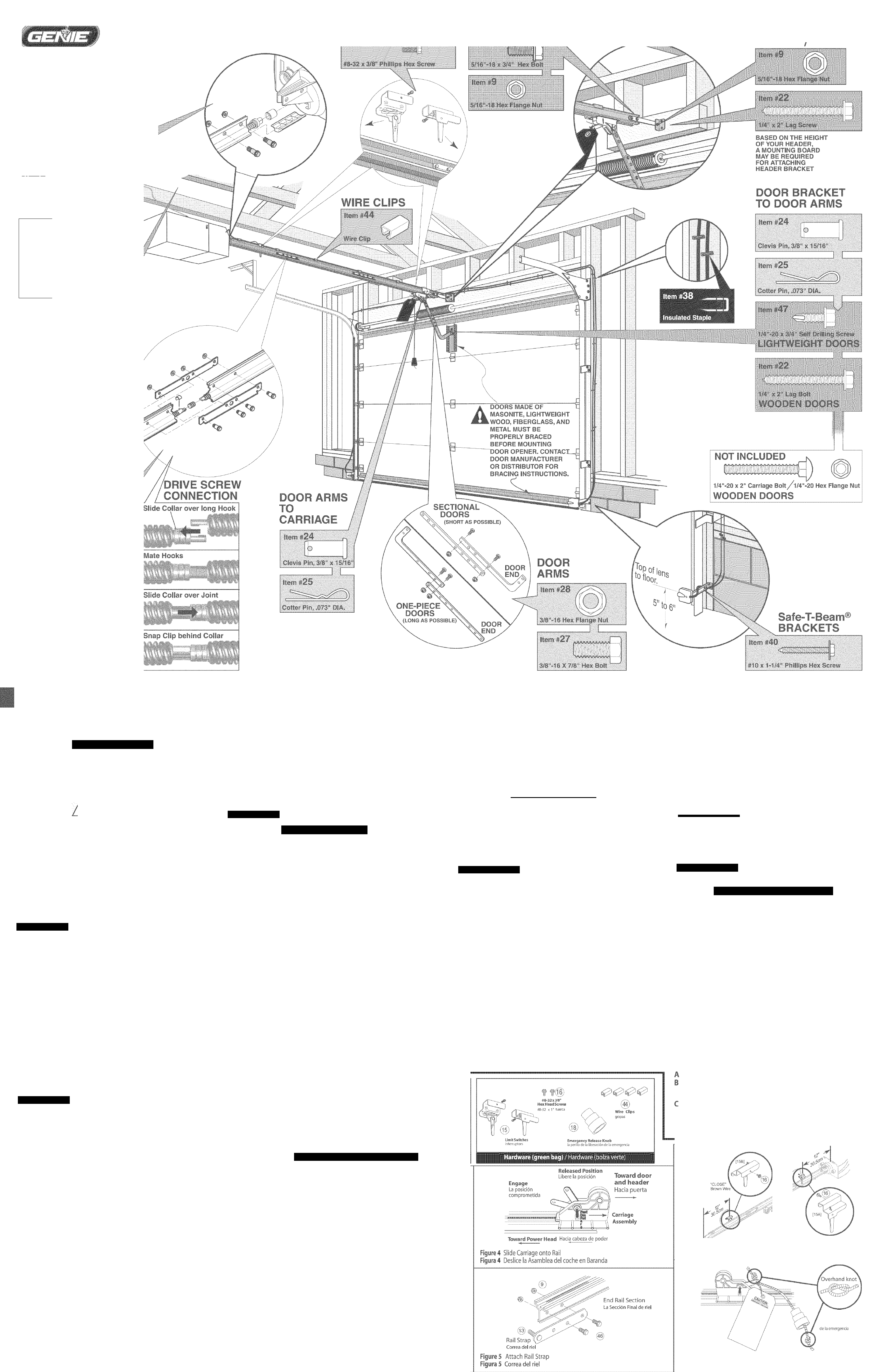
READ OWNER'S MANUAL COMPLETELY PRIOR TO INSTALLATION
^miL HEADER /rail
: 1 BRACKET/ STRAP
TENERS* SHOWN 0 ÎIZE
RAIL TO
POWER
HEAD
ilfiiiiiSi
eltiiBliSiSittp
I wo wo X
not
'ïALL
6 ROL
vin Head Screws
■wn (Red bag)
pifes:
ii#
t'ijJiS
•sSJjífcs
íHSiM. 'jSlísS
IljCTJ^icpT
iiiil
:sÍSS
lili
íilH SsilÉ IIS
...
Ri:?
..
>N
c:
fO
Cl
E
O
U
.S¿
*c
û)
kD
dj
<
m
Q
ü
C
en
c
Ju
O
X
iD
KO
8
fN
O
ALEEL Ensamble del Corredizo Magíétícoa
íaraídas
â
B
OPEN BLUE PARTS BAG
Turn Power Head so that front panel (with end of shaft and rail
attachment flange) is facing up and place on a fiat level surface.
Install Coupler on Motor Shaft (Figyre 1).
" Place Coupler over end of shaft.lurn it until it drops down over
the shaft.
" Lay Power Head on its bottom.
C CAUTION
The Drive Screw can slide ouï of Rail Sections. Keep Rail Sections level
until the Opener is fully assembled.
Connect first Raii Section [with bearing {Figure 1)i to Opener Power
Head
* Slide Drive Screw so that bearing end extends several inches
out of rail.
* insert bearing end of Screvv' into Coupier.
* Slide Rail into attachment flange and align holes.
* Connect with 2 (l/4"-20) Hex Head Shoulder Boils and 2 (1/4" -
20) Hex Serrated Flange Nuts (Figure 2J. Fiiiger-tighten until
later.
Slide carriage stop into rail and up against the power head.
Assembly Step 2
Ikstall remaihing Raíl Sections
Artange arrows on Raii Sections to point in .same direction and away
from Power Head. (Middle rail same on both ends.)
* Connect Screw sections;
- Push Middle Drive Screw out about 2" roward Power Head.
- Slide Collar over Middle Drive Screw Hook (Figure 3A).
- Turn Middle Screw by hand to align Drive Screw Hooks
between First and Middle Raii Sections.
- Latch two Hooks together and slide Collar over them
(Figyre 3B) and (Figure 3C).
- Snap Clip on Drive Screw next to Collar (FigureSD).
Attach Middle Rail Section to First Raii Section, using 2 Rail Clamps,4
(5/16“-18) Hex Shoulder Bolts, and 4 (5/16"-18) Hex Head Serrated
Flange Nuts (Figyre 3). Finger tighten yntil later.
NOTE
If a Rail Extension is needed, attach it now per the instructions
included with the Kit.
C Attach End Rail Section to Middle Rail Section following proc:edure.s
in Step A &B,
Assembly Step 3
ÍKSTALL Carriage
A Flip Power Head / Rail Assembly upside down so that entire length
of the screw is visible.
B Slide Carriage Assembly into slot on End Rail Section with arrow
pointing away from the Power Head (Figure 4).
Power Head
Assembiy
Accione la a-semclea .
dé cabe??.
Tc'ì
” ‘ ' ri '.V<Tx' Il .
Il’-.-A'» / ■ 'V-.;
Tri /■ ■■
m •
fk'-tl-yj
i- ’XÜ'Jñ
pNIi^i ) 'riCiOn
d'> l.-;r.irid-i
A'
!T-
r:?- ^
■ Coupier-T
'¿\ EJCOpbdur
I ,• .5^.,
rrrrsdgt'
h ilT. ìC ' -A I i.
r>-
Figure 1 Instali Coupler and I st Raìi Seaiun T
Figura 1 Instale e! aropladcf v prirnero rión rie irurarria ¡' ”
- .< V I
V. Il
- i
(■CT';
Figure 2 riolr i st Kail Section to Power Head
Figura 2 Cié re phmero sección de baranda a id cabeza de! poder
B Tighten snugly but Do Not overtighten.
Ü
__________
A Align al! Rail Sections so Carriage Assembiy can slide freely along
length of Rail.
B Securely tighten all fasteners now. Do Not over-tighten.
Assembly Step 6
i MSTALL AND CONNECT LlMlT SWITCHES
OPEN GREEN PARTS BAG
^ rium Opener right side up.
B Place Switches on Rail (Figure 6). (Switches are identicai.)
■ i’iace one switch about 1 "*"from Rail Strap end of Rail, so that
the white trigger is toward Power Head. (Standing at Raii Str.ap,
looking toward Power Head, Switch wd!! be on left side of Rail,)
This is the "CLOSE" Switch.
■ Insert set screw into Sv^itth and finger tighten only to
temporarily hold Switch in place.
■ Connect Brown Wire to this S'witch.
- Leaving a little slack in the Wire, run it down the groove in
top of fell to'A/ard Power Head.
• Place remaining Switch about 12"from Power Head so that it
hangs on opposite side of Rail from first switch.This is the
“OPEN"Switch.
• Insert set screw into Switch and finger tighten only to
temporarily hoid Switch in place.
• Connect Gray Wire to this Switch.
- Leaving a little slack in the Wire, run it down the groove in
top of Raii toward Power Head.
C Coil remaining Wire on top of Power Head and tape down.
AND Knob
A Tie overhand knot at one erjd of emergency release cord and
puli cord through the hole in the release lever up to the knot.
(Figuji'e 2 (
B Thread oppo.site end of cord through knob and tie a knot in this
end also.
C After installation of your ejarage door opener, adjust the
height of the knob to no less than 6 feet above the floor.
*The Emergency Release Cord is threaded through the Carriage
release lever at the taciory
A PRECAUTION
El Tornio de transmisión y el forro dei riel pueden deslizarse fuera de las )
secciones del riel. Mantenga las secciones del riel horizontales hasta que el ,
afarepuertas de ia puerta esté ensamblado completamente. '
C Ensamble !a primera sección del riel a la caja del motor del abrepuertas.
Aíornilíe con 2 pernos con tope de cabeza hexagonal de (1/4 "-20] y 2
tuercas de reborde hexagonal (l/4"-20¡ (Figura 2). Apriete manuaímerite.
pl Deslice la parada de! coche en la baranda y contra el poder diringe.
Asamblea da Paso 2
r
ÍNSTALACION de las SeCCÍOMES ADICiOMALES DE LA
BmmDA
B
Acomode las fiecha.s de ias secciones de baranda de manera que todas apunten en !a
misma dirección y hada afuera de !a caja dei motor,
* Conecte las secciones del tornillo.
- Saque ei tornillo de transmisión intermedio aproximadamente
2''hada !a caja del motor.
- Deslice el collar sobre el gancho del tornillo de transmisión
intermedio (Figyra 3A).
- Gire ei torRillo iRtermedio a mano para alinearlo co.n ios ganchos de!
tornillo de transmisión entre ias secciones primera e intermedia,
- .Asegure dos ganchos juntos y deslice eí callar sobre ellos
(Figura 3B) y (Figura 3C).
- Cierre el clip sobre e! tornillo de transmisión cerca del collar,
(Figura 3D).
Junte !a sección intermedia de baranda con la primera sección, usando 2
abrazaderas de riel, 4 pernos de tope hexagonal (5/16 "-18) y 4 tuercas de
reborde hexagonal (5/16"-18) en ios pernos (Figura 3). Apriete
m.anuaimeníe,
NOTA
S¡ se requiere el ensambie Extensión (GSXL8), instálelo
siguiendo las instrucciones proporcionadas en el paquete.
C Junte !a sección fina! de ia baranda con la sección intermedia siguiendo los
procedimientos descritos en ¡os pasos A y B,
L4--Ülf=-:'dc k' briH
13,' .-T V
"í' ' Cto.
A-'Ó-TT'-
'■'tíT
Can'i^qe Slop
Pifada coche
5/1 fí’- Itì Hex H§î5d ShCHuidef Bolts
ÿyyydafT
Íü^rc.-í déî ¡eboEü-,' - [ •
cieiiioda fievEgor.-il ^ '
deS/íó"-18 "
Hií-ic
SetTtîîod
,
ífi ■
i/4'‘-*iQHéK Hiíad
Shi?í2kli?r Boiüa. iÿififeiw)
y?
Tuerca de ¡r horde
driiitadn liCrtgoric!
dei/4"rt0 "
S/5é’"18 H&íL Swr.oted í•lэfîgtf^Jut5
fOuE4;îioÇuf|
fuerce de reborde
ci'inLadíí írt/!oOui:j| I 9 '
de 2.'i0'MR '
'■.f-ÍV ’
Coupler
A:opi£i'Joi
Tiifmr a (¡f
d'£''L3Ck' iie/agr..sal
‘■rt, i.u;
Collars-'Spare
çuelios y rtservü
Head Bolts
í ' ‘ m
'C'-.f. ~ wma
OH Í4
cabeza
'■iT'
fetaifiirsq CHps +ip2(so
pipes que ret'enen y reserva
Hardware (blue bag) / Hardware (bolza azulea)
'> \ ;i h'ùn ./'Vh^r: nr< k ij.-ifiri
'-■'é
Rerainir-fi Clip.â
ÇJ
m
Í.
Eldpqíií; eî.en
/
/ >
A. row*. №a';msî . '
ifn'rjue:'... v-rU.-. poil- ■*“ ^ .[
Middi« teii
Sâctt&n
.* '^cciiin m¡
iH h.*iTr Í1'*],,
I
3A. .-lip'jiM.m !’v
- "h
Je'j’.'.t. tUtlL . n üdiiLhO ,1,'.
ColGz
‘ ' ,'iif-üj
,Bi. ff'Uoqt! )■'jop
■ -f '
..J '
<'.iii;-nirfr''iic' n-i !.‘"j
1C. Siili; Lî,|.!I OVl-î ri-.'Oi.S
P f ..Ufo V ;>r^ ' snOt'i
iD. ■•ricìp un líf-LiiPmi'í Zlif,
W ^ m. T_.
Figyre 3 Attach Middle Raii Section
Figuf/i T ^onecte la seedón mediana de baranda
ei corredizo en la posición "liberar"
zo en la ranura en la serción final de barand con la
irecdón opuesta a la caja de! motor (Figyra 4],
TE LA ÍANBA D£ Baü ANDA AL LA SECOÓi FiNAL
DE KARAi^DA
A Sujete la banda del riel a !a sección fin.al de! riel u.sando 2 per nos de cabeza
hex.agonal de (5/16 "-1B) y 2 tuercas de reborde hexagonal (5/16 "-13) (Figura 5),
B Aprie te firmemente cuidando no sobreapretarios.
Asamblea da Paso 5
I
Auíiee ias Seccíóíes de la Baranda y apriete
TODOS LOS Pernos
A .Alinee todas las secciones de! .riel de manera que e! ensamble del corredizo
magnético pueda deslizarse libremente a lo largo de la longitud de! riel.
B Apriete firmemente todos los pernos cuidando no sobreapretarios.
Asamblea da Paso 6
I
Instale y Conecte los Imterruptors de los
Límites de Cíerre y Apertura
ABRA LA BOLZA VERDE DE PARTES
A Gire al Operario boca arriba.
B Coloque swithces en !a baranda (Figura 6). (Interruptores son idénticos.)
• Coloque un interruptor aproximadamente 12 pulgadas del fin de
correa de baranda de la baranda, para que el disparador blanco
e,stén hacia la cabeza de! poder. (Airándose en la correa de baranda,
mirando !a cabeza del poder,ei inlerruptor estará en e! iado
izquierdo de la baranda.) Esto es el interruptor CERCANO.
• Meta el torniiío fijo en el interruptor y e! dedo aprieta para sólo
tener temporalmente el interruptor en ei lugar.
‘ Conecte el alambre marrón a e.ste interruptor.
“ Saliendo un pequeño flojo en ei alambre, !o corre abajo la
ranura en la cima de ia baranda hacia ia cabeza del poder.
• Coloque el quedándose cambia aproximadamente 12 pulgadas
de la Cabeza del Poder para que cueigue en ei lado opuesto de
Í3 baranda del primer interruptor. Esto es el interruptor ABIERTO,
• Meta ia tripulación fija en el interruptor y el dedo aprieta para sólo
tener temporalnienle e! interruptor en el lugar.
• Conecte e! alambre gris a este iníerruptor.
- Saliendo un pequeño flojo en e! alambre, !o corre abaje* ranu.ra
en !a cima de la baranda hacia ia cabeza del poder.
C Enrolle el remaiinincj aiartibre encima de ía cabeza de! poder y ío graba
hacia abajo.
Asamblea da Paso 7
^ Cterda*
Haga un medio nudo en un extremo de !a cuerda de liberación de emergencia.
Ensarte el extre.mo opuesto de ia cuerda a través de ia manija y en el
agujero de ía palanca de liberación dei ensamble del corredizo magnético
(Figure 7).
Desputes de que la instalación de su abridor de puerta de garaje,
adjusta la altura de la perilla a no menos de 6 pies encima del piso.
* La Cuerda de ia Liberación de ia Emergencia se enhebra por la
palanca de fa liberación del corredizo en la fábrica.
'■r.FF.V
C5t"c/ Wiro
Figure ó install Limit Switches on Assembled Rai!
Figyra 6 Instale los Interruptores de los Lirriftes
ReleaitôTag
LeetiquecA deb líbeíD-Dónde
ci:'* eiTHrgeT'Crt
Emfâigency Relcaiíe Knob
Lei Pnrilb de k i'beretmtn
Figure 7 Attach Emergency Release Cord/Knob and Tag
Figura 7 Conecte la Emergencia Cuerda de Liberación y Etiqueta
 Manymanuals.com
 Manymanuals.de
 Manymanuals.fr
 Manymanuals.it
 Manymanuals.pl
 Manymanuals.cz
 Manymanuals.es
 Manymanuals-pt.com
Comments to this Manuals