Genie M-4700 User Manual Page 17
- Page / 32
- Table of contents
- BOOKMARKS
- This product 1
- January 1,1993 1
- OWNER’S MANUAL CONTENTS 2
- 2. ADVANCED FEATURES 3
- 1. INTRODUCTION 3
- 4. TOOLS 4
- 5. GARAGE AND DOOR 4
- 5. GARAGE AND DOOR (cont’d) 5
- 6. OPENER PACKAGE CONTENTS 6
- 8-2. INSTALL HEADER BRACKET 8
- 8. INSTALLATION STEPS 8
- A. FOR SECTIONAL DOORS: 9
- B. FOR ONE-PIECE DOORS: 9
- DOORS ONLY: 10
- DOORS WITH TRACK: 11
- 8-7. MOUNT OPENER TO CEILING 12
- 8-9. CHECK EMERGENCY RELEASE 13
- FOR BOTH TYPES OF MOUNTING: 14
- (cont’d) 15
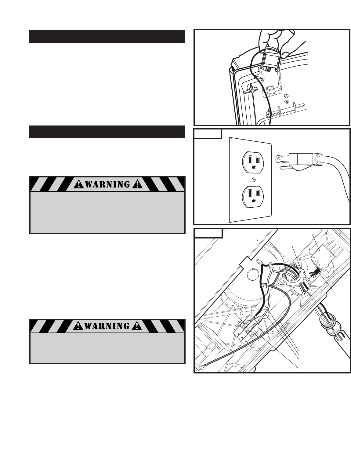
- 8-15. MODULAR RECEIVER 17
- 8-16. CONNECT TO POWER 17
- 8-18. SET THE ADJUSTMENTS 18
- 8-17. CONTROL PANEL 18
- OPEN TRAVEL LIMIT (Fig. 39): 19
- CLOSE TRAVEL LIMIT (Fig. 40): 19
- UP FORCE (Fig. 41): 19
- DOWN FORCE (Fig. 42): 19
- TRANSMITTER CODING (Fig. 43): 19
- 8-19. TEST SAFETY REVERSAL 20
- IMPORTANT SAFETY 21
- INSTRUCTIONS 21
- OR DEATH: 21
- 10. TRANSMITTERS 22
- 11. OPERATION OF YOUR OPENER 23
- 12. HOMELINK 23
- TRANSCEIVER 23
- 14. RAIL LENGTH ADJUSTMENT 24
- 13. TENSION ADJUSTMENT 24
- 15. SYSTEM PARTS 25
- 15. SYSTEM PARTS (cont’d) 26
- 15. SYSTEM PARTS (cont‘d) 27
- 16. ACCESSORIES 28
- 17. HAVING A PROBLEM? 29
- 20. MAINTENANCE RECORD 31
- 1-888-622-2489 32
Related products and manuals for Garage Door Opener Genie M-4700

 (29 pages)
 (26 pages)
© 2020, manymanuals.com. All rights reserved. | 0.251 s |
 Manymanuals.com
 Manymanuals.de
 Manymanuals.fr
 Manymanuals.it
 Manymanuals.pl
 Manymanuals.cz
 Manymanuals.es
 Manymanuals-pt.com
Comments to this Manuals